Old Pueblo Engineering Center
Founded 2006 in Tucson, AZ. to explore Human/Robot Interactivity
“Drilling Brains for a New & Better Use of Technology”
Patents Pending

HOME

Ready-2-Play Robotics
5t4nd1ng @ th3 3dg3 0f 5p3ct4t10n!

Give a child a toy and they're happy for an hour.
Teach a child how to make their own toys, and they're happy for life!


Connecting to a LED
Light Emitting Diode

Light = electromagnetic radiation within a certain portion of the electromagnetic spectrum.
Emitting = sending out, expelling
Diode = a PN junction of two semiconductor materials such as galium and arsnic

Source: wiki

For most components there is a Signal PIN, a + PIN and a - or ground PIN

A basic LED (Light Emitting Diode) has the + and -/Gnd pins and the light is the signal emitted out

You may have a common anode or common cathode LED


The flat side of the base denotes the cathode pin side

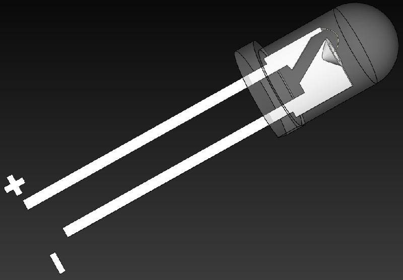
Typical common cathode LED

As the a pin is either pulled LOW or HIGH by the MCU pin the LED turns ON

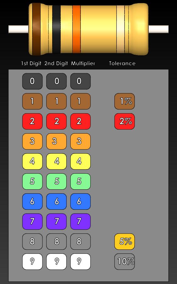
Typically a 200 Ohm up to maybe 1K Ohm resistor in series
limits the current so the LED does't burn out


Resistor Chart 10KΩ Resistor Example


See the lesson picture, put the wires on the same way, then click on the picture to copy/paste the program code for that lesson into the FREE BASIC language Editor to program the chip to perform the lesson. 

After going through a few of the lessons, come back to this first lesson and start making changes to the program code … move the jumper wire from PIN B.1 to maybe PIN B.7 change the program code from "symbol LED = B.1" to "symbol LED = B.7"  and see the lesson function again.


Now change the line: "pause 250 ; wait 1/4 second" to be "pause 100 ; wait 0.1 second"

ReProgram the chip and watch the lesson function.